
Products Events
Home > News > Products Events > CoLIS-HP Series 1550...
CoLIS-HP Series 1550nm Long Pulse Single Frequency PM Fiber Laser
Time:2019.01.11 Source: Author:
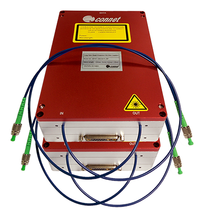
Connet CoLIS-HP series 1550nm nanosecond long pulse single-frequency
polarization-maintaining fiber laser is a modularized pulsed fiber laser
specially designed for long-distance coherent Doppler wind lidar
application. This fiber laser is for long-pulse applications (100ns-2us)
based on eye-safe operating wavelength. The output laser is the
single-mode linear polarization with the output single-pulse energy up
to 150uJ.
CoLIS-HP
series 1550nm nanosecond long pulse single-frequency
polarization-maintaining fiber laser internally integrates with Connet’s
proprietary single-frequency narrow linewidth seed laser source with
the linewidth narrow to 5kHz. The extinction ratio can be up to 100dB or
more through the cascaded acousto-optic modulator (AOM) to produce a
pulse signal with high turn-off ratio.
Connet
CoLIS-HP series 1550nm nanosecond long pulse single-frequency
polarization-maintaining fiber laser adopts all PM fiber design and can
achieve the high polarization extinction ratio (PER) output. The output
end can be integrated with high power three-port optical circulator
according to the application requirements.
Features:
• Eye-safe Wavelent: 1550nm
• Single Pulse Energy: up to 150uJ
• Adjustable Repetition Rate: 5-20kHz
• Pulse Width: 100-2000ns
• Single-mode Output
• High PER
Applications:
• Coherent Doppler Wind LiDAR
• Environmental Monitoring
• Pollution Monitoring
• Other Scientific Research
Main Test Data:
|
Parameter |
Unit |
Test Result |
|
|
Pulsed Fiber Laser Module |
|||
|
Operating Wavelength |
nm |
1549.780 |
|
|
Local Oscillator Output Power (Tap End) |
mW |
4.3 |
|
|
Pulse Output Power |
@200ns/10kHz |
uW |
22 |
|
@300ns/10kHz |
35 |
||
|
@400ns/10kHz |
50 |
||
|
@1000ns/5kHz |
70 |
||
|
Linewidth |
kHz |
<10 |
|
|
SMSR |
dB |
47 |
|
|
Relative Intensity Noise (RIN) @1MHz |
dBc/Hz |
<-130 |
|
|
Phase Noise |
@10Hz |
µrad/√Hz/m |
<400 |
|
@100Hz |
<300 |
||
|
@1kHz |
<30 |
||
|
@10kHz |
<3 |
||
|
Beam Quality |
M2 |
<1.05 |
|
|
Output Power Stability |
% |
<2 |
|
|
Polarization Extinction Ratio (PER) |
dB |
>20 |
|
|
Input/output Isolation |
dB |
>30 |
|
|
Pulse Extinction Ratio |
dB |
>100 |
|
|
Pulse Width (Full Pulse Width) |
ns |
200~1000 |
|
|
Repetition Rate |
kHz |
5~10 |
|
|
Frequency Shift |
MHz |
+80 |
|
|
RF Signal Input |
Impedance |
|
High Impedance |
|
High Level |
v |
3.3~5 |
|
|
Low Level |
v |
0 |
|
|
Output Fiber Type |
|
PM1550-XP |
|
|
Output Fiber Connector |
|
FC/APC |
|
|
Output Fiber Length |
m |
1 |
|
|
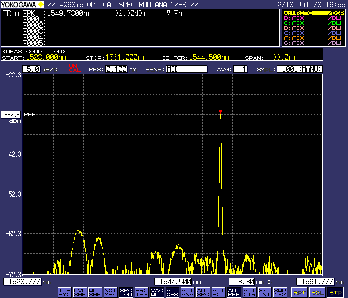
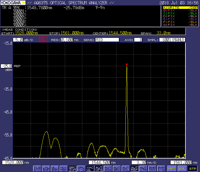
Output Spectrum (TAP End) |
|
See Fig. 2 |
|
|
Ouput Pulse Waveform |
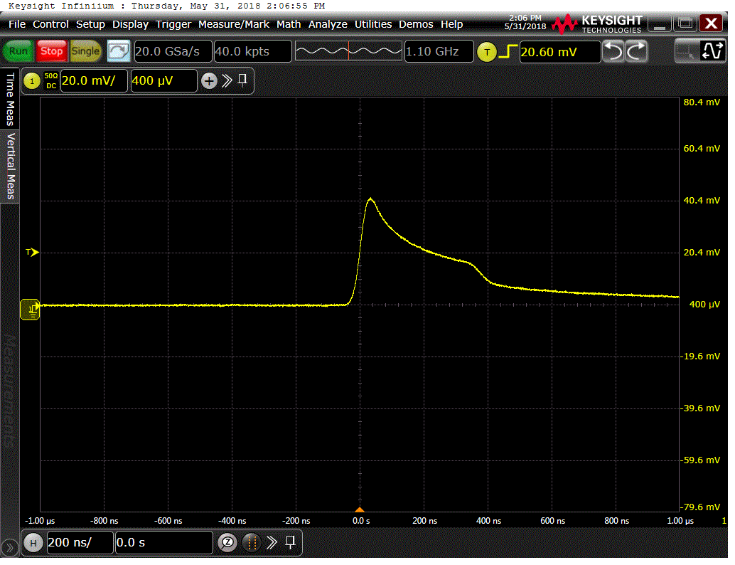
@200ns/10kHz |
|
See Fig. 3 |
|
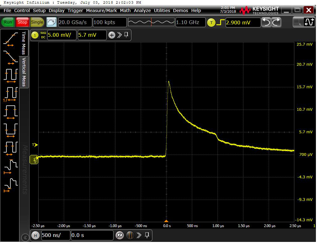
@300ns/10kHz |
See Fig. 4 |
||
|
@400ns/10kHz |
See Fig. 5 |
||
|
@1000ns/5kHz |
See Fig. 6 |
||
|
Pulsed Fiber Amplifier Module |
|||
|
Output Average Power @200ns/10kHz @Pump Power 11500mW |
@25℃ |
W |
1.1 |
|
@-40℃ |
1.2 |
||
|
@60℃ |
1.05 |
||
|
Output Average Power @300ns/10kHz @Pump Power 14500mW |
@25℃ |
W |
1.5 |
|
@-40℃ |
1.55 |
||
|
@60℃ |
1.44 |
||
|
Output Average Power @400ns/10kHz @Pump Power 17000mW |
@25℃ |
W |
1.8 |
|
@-40℃ |
1.85 |
||
|
@60℃ |
1.6 |
||
|
Output Average Power @1000ns/5kHz @Pump Power 13000mW |
@25℃ |
W |
1.3 |
|
@-40℃ |
1.35 |
||
|
@60℃ |
1.25 |
||
|
Measured Single Pulse Energy @25℃ |
@200ns/10kHz |
uJ |
100 |
|
@300ns/10kHz |
140 |
||
|
@400ns/10kHz |
162 |
||
|
@1000ns/5kHz |
223 |
||
|
Beam Quanlity |
M2 |
<1.3 |
|
|
Output Power Stability |
% |
<5 |
|
|
Polarization Extinction Ratio (PER) |
dB |
>18 |
|
|
Input/3-port Circulator Fiber Type |
|
PM1550-XP |
|
|
Input/3-port Circulator Fiber Connector |
|
FC/APC |
|
|
Input/3-port Circulator Fiber Length |
m |
1 |
|
|
Output Fiber Type |
|
PLMA-GDF-25/300 |
|
|
Output Fiber Connector |
|
FC/APC |
|
|
Output Fiber Length |
m |
0.35 |
|
|
Input Isolation |
dB |
>30 |
|
|
Output Isolation |
dB |
>20 |
|
|
Output Pulse Waveform |
@200ns |
|
See Fig. 7 |
|
@300ns |
See Fig. 8 |
||
|
@400ns |
See Fig. 9 |
||
|
@1000ns |
See Fig. 10 |
||
|
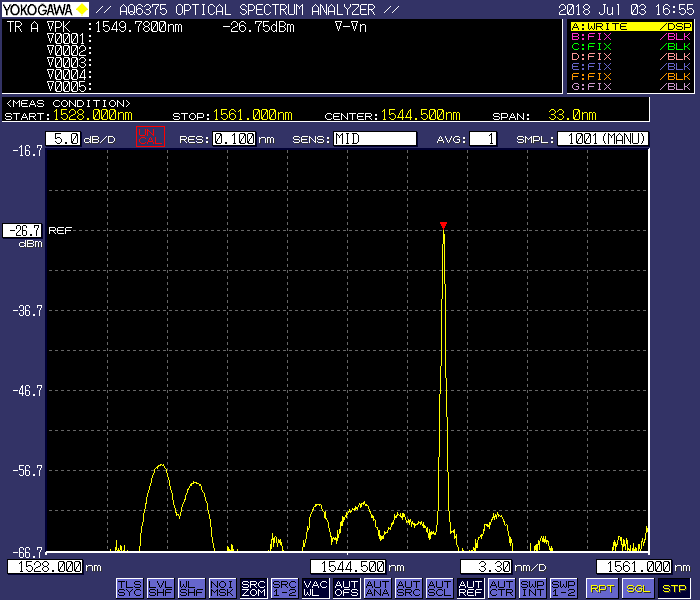
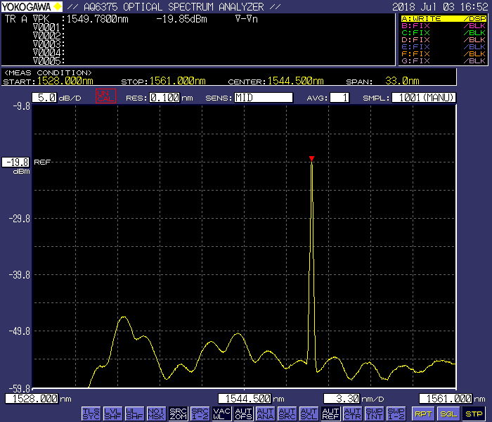
Output Spectrum |
@200ns |
|
See Fig. 11 |
|
@300ns |
See Fig. 12 |
||
|
@400ns |
See Fig. 13 |
||
|
@1000ns |
See Fig. 14 |
||
Notes:
- The test results of the output power were measured with the fiber connector.
- Since there are two overlaying AOMs inside the pulsed laser, the pulse width set on the function generator is different from the actually measured pulse width. The test is based on the measured full pulse width. Here list some tested typical values for reference: setting 244ns corresponds to the full pulse width of 200 ns; setting 340 ns corresponds to the full pulse width of 300 ns; setting 440 ns correspond to the full pulse width of 400 ns; setting 1040 ns, corresponds to the full pulse width of 1000 ns.
Product Information and Main Test Equipment:
|
Product |
1550nm Long Pulse Single Frequency PM Fiber Laser (For Long-distance Wind Measurement) |
|
P/N |
CoLIS-1550-M-SF-HP |
|
S/N |
201805086 |
|
Main Test Equipment |
Power Meter (OPHIR, NOVA II) |
|
Energy Meter (OPHIR, PE9-C) |
|
|
OSA (YOKOGAWA, AQ6375) |
|
|
Oscilloscope (KEYSIGHT, DSOS104A, 1G) |
|
|
1G Detector (THORLABS, DET08CFC/M) |
|
|
Function Generator (RIGOL, DG5101) |
Test Environment and Power Supply:
|
Parameter |
Specification |
|
|
Power Supply |
12-24VDC |
|
|
Communication Interface |
RS232 |
|
|
Operating Temperature |
Pulsed Fiber Laser |
00C ~ +500C |
|
Pulsed Fiber Amplifier |
-400C ~ +600C |
|
|
Ambient Temperature |
<90% |
|
|
Test Temperature |
Pulsed Fiber Laser |
00C ~ +500C |
|
Pulsed Fiber Amplifier |
-400C ~ +600C |
|
| Ambient Humidity |
<90% |
|
Schematic Diagram of Test:

▲ Fig. 1 Schematic Diagram of Simultaneous Measurement for Power, Spectrum and Pulse Waveform
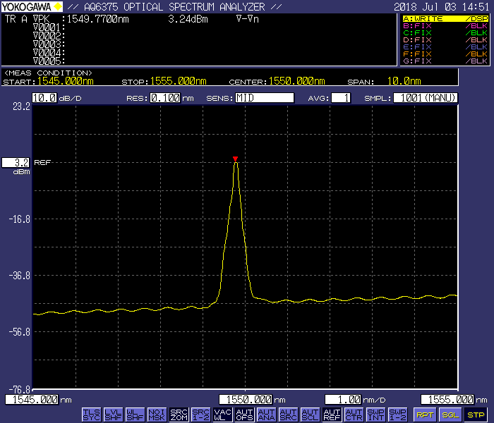
▲ Fig. 2: Output Spectrum of Laser @TAP End
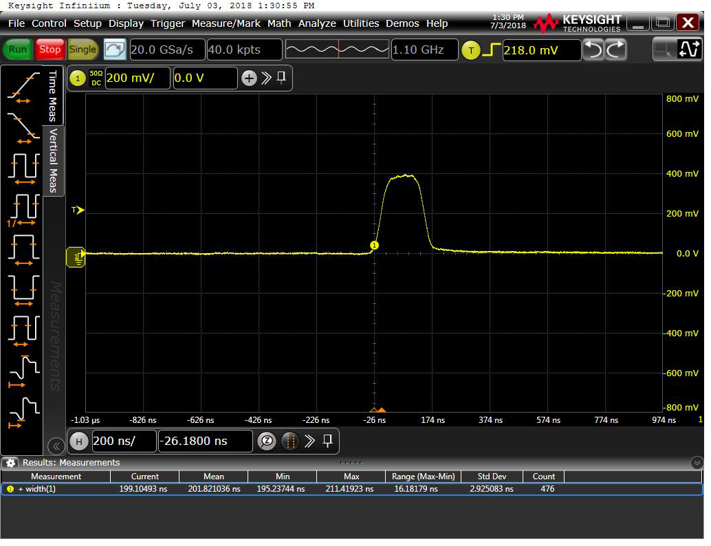
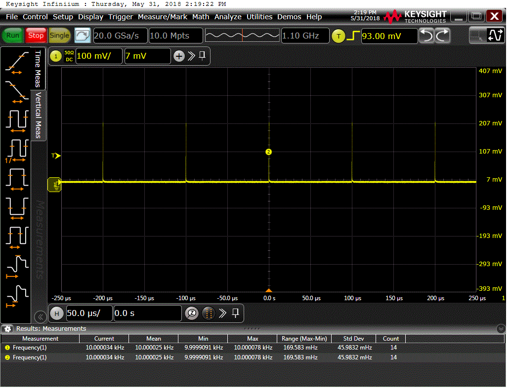
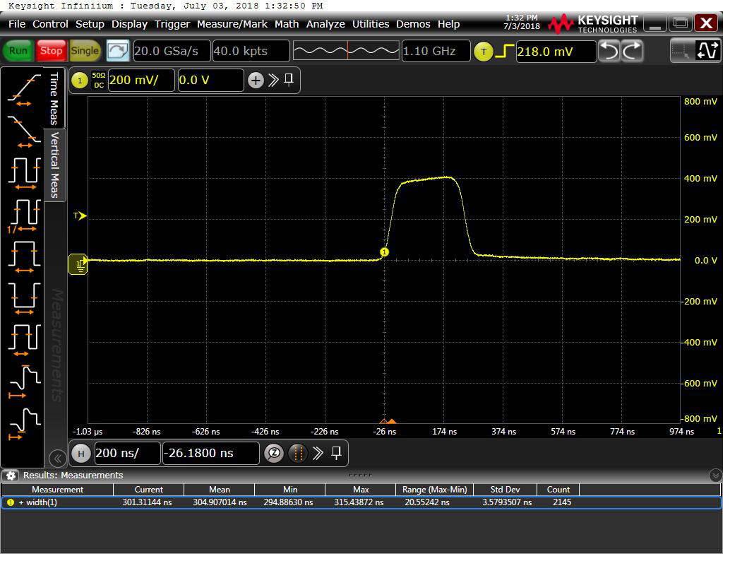
▲ Fig. 3: Ouptut Pulse Waveform of Laser @200ns/10kHz
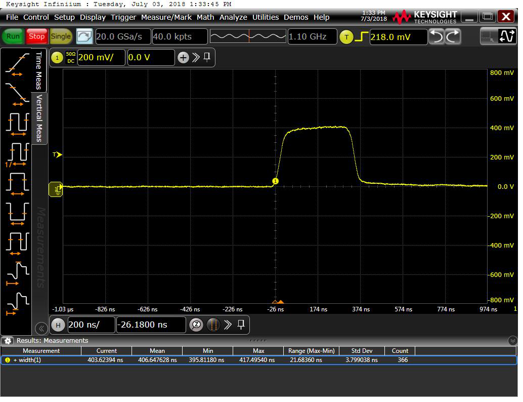
▲ Fig. 4: Ouptut Pulse Waveform of Laser @300ns ▲ Fig. 5: Ouptut Pulse Waveform of Laser @400ns
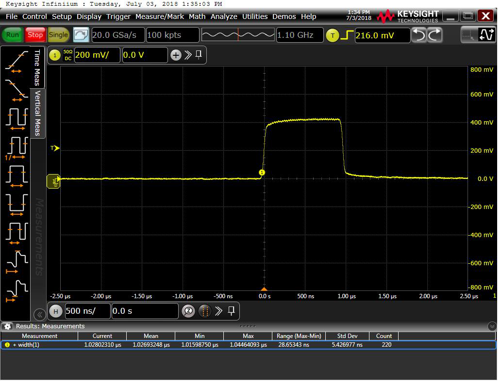
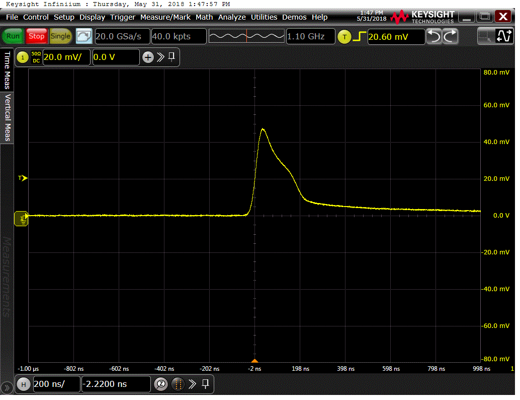
▲Fig. 6: Ouptut Pulse Waveform of Laser @1000ns ▲Fig. 7: Ouptut Pulse Waveform of Amplifier @200ns

▲ Fig. 8: Ouptut Pulse Waveform of Amplifier @300ns ▲Fig. 9: Ouptut Pulse Waveform of Amplifier @400ns
▲ Fig. 10: Ouptut Pulse Waveform of Amplifier @1000ns ▲ Fig. 11: Output Spectrum of Amplifier @200ns
▲ Fig. 12: Output Spectrum of Amplifier @300ns ▲ Fig. 13: Output Spectrum of Amplifier @400ns
▲ Fig. 14:Output Spectrum of Amplifier @1000ns